
 danny wang
6b2cb6fa39
this N3 net clean robot use bfd1.5V6
danny wang
6b2cb6fa39
this N3 net clean robot use bfd1.5V6
|
2 năm trước cách đây | |
|---|---|---|
| .. | ||
| PixhawkLabeled.jpg | 2 năm trước cách đây | |
| README.md | 2 năm trước cách đây | |
| hwdef-bl.dat | 2 năm trước cách đây | |
| hwdef.dat | 2 năm trước cách đây | |
README.md
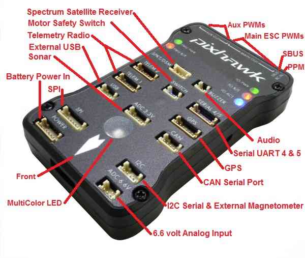
Pixhawk1 Flight Controller
The Pixhawk1 flight controller was originally produced by 3DR. A number of vendors now sell boards with the same layout as the original board.
Features
- STM32F427 microcontroller
- MPU6000 and LSM303D/L3GD20 IMUs
- MS5611 SPI barometer
- builtin SPI LSM303D magnetometer
- microSD card slot
- 5 UARTs plus USB
- 14 PWM outputs
- I2C and CAN ports
- Spektrum satellite connector
- External Buzzer
- builtin RGB LED
- external safety Switch
- external SPI port
- voltage monitoring for servo rail and Vcc
- dedicated power input port for external power brick
- external USB connectors (micro USB and DF13)
Pinout
UART Mapping
- SERIAL0 -> USB
- SERIAL1 -> UART2 (Telem1)
- SERIAL2 -> UART3 (Telem2)
- SERIAL3 -> UART4 (GPS)
- SERIAL4 -> UART8 (GPS2)
- SERIAL5 -> UART7 (spare)
The Telem1 and Telem2 ports have RTS/CTS pins, the other UARTs do not have RTS/CTS.
The GPS2/spare port (labelled serial5) has two UARTs on one 6 pin connector. The spare port was originally used as a debug console, but debug is now on USB, so this port is free for any UART protocol.
Connectors
The original Pixhawk1 uses DF13 connectors, and has 14 ports
TELEM1, TELEM2 ports
| Pin | Signal | Volt |
|---|---|---|
| 1 (red) | VCC | +5V |
| 2 (blk) | TX (OUT) | +3.3V |
| 3 (blk) | RX (IN) | +3.3V |
| 4 (blk) | CTS | +3.3V |
| 5 (blk) | RTS | +3.3V |
| 6 (blk) | GND | GND |
GPS port
| Pin | Signal | Volt |
|---|---|---|
| 1 (red) | VCC | +5V |
| 2 (blk) | TX (OUT) | +3.3V |
| 3 (blk) | RX (IN) | +3.3V |
| 4 (blk) | CAN2 TX | +3.3V |
| 5 (blk) | CAN2 RX | +3.3V |
| 6 (blk) | GND | GND |
SERIAL 4/5 port
| Pin | Signal | Volt |
|---|---|---|
| 1 (red) | VCC | +5V |
| 2 (blk) | TX (#4) | +3.3V |
| 3 (blk) | RX (#4) | +3.3V |
| 4 (blk) | TX (#5) | +3.3V |
| 5 (blk) | RX (#5) | +3.3V |
| 6 (blk) | GND | GND |
ADC 6.6V
| Pin | Signal | Volt |
|---|---|---|
| 1 (red) | VCC | +5V |
| 2 (blk) | ADC IN | up to +6.6V |
| 3 (blk) | GND | GND |
ADC 3.3V
| Pin | Signal | Volt |
|---|---|---|
| 1 (red) | VCC | +5V |
| 2 (blk) | ADC IN | up to +3.3V |
| 3 (blk) | GND | GND |
| 4 (blk) | ADC IN | up to +3.3V |
| 5 (blk) | GND | GND |
I2C
| Pin | Signal | Volt |
|---|---|---|
| 1 (red) | VCC | +5V |
| 2 (blk) | SCL | +3.3 (pullups) |
| 3 (blk) | SDA | +3.3 (pullups) |
| 4 (blk) | GND | GND |
CAN
| Pin | Signal | Volt |
|---|---|---|
| 1 (red) | VCC | +5V |
| 2 (blk) | CAN_H | +12V |
| 3 (blk) | CAN_L | +12V |
| 4 (blk) | GND | GND |
SPI
| Pin | Signal | Volt |
|---|---|---|
| 1 (red) | VCC | +5V |
| 2 (blk) | SPI_SCK | 3.3V |
| 3 (blk) | SPI_MISO | +3.3V |
| 4 (blk) | SPI_MOSI | +3.3V |
| 5 (blk) | !SPI_NSS | +3.3V |
| 6 (blk) | !GPIO | +3.3V |
| 7 (blk) | GND | GND |
POWER
| Pin | Signal | Volt |
|---|---|---|
| 1 (red) | VCC | +5V |
| 2 (blk) | VCC | +5V |
| 3 (blk) | CURRENT | up to +3.3V |
| 4 (blk) | VOLTAGE | up to +3.3V | 5 (blk) | GND | GND | 6 (blk) | GND | GND |
SWITCH
| Pin | Signal | Volt |
|---|---|---|
| 1 (red) | VCC | +3.3V |
| 2 (blk) | !IO_LED_SAFETY | GND |
| 3 (blk) | SAFETY | GND |
RC Input
RC input is configured on the RCIN pin, at one end of the servo rail, marked PPM in the above diagram. This pin supports all RC protocols. In addition there is a dedicated Spektrum satellite port which supports software power control, allowing for binding of Spektrum satellite receivers.
PWM Output
The Pixhawk1 supports up to 14 PWM outputs. First first 8 outputs (labelled "MAIN") are controlled by a dedicated STM32F100 IO controller. These 8 outputs support all PWM output formats, but not DShot.
The remaining 6 outputs (labelled AUX1 to AUX6) are the "auxillary" outputs. These are directly attached to the STM32F427 and support all PWM protocols as well as DShot.
The 8 main PWM outputs are in 3 groups:
- PWM 1 and 2 in group1
- PWM 3 and 4 in group2
- PWM 5, 6, 7 and 8 in group3
The 6 auxillary PWM outputs are in 2 groups:
- PWM 1, 2, 3 and 4 in group1
- PWM 5 and 6 in group2
Channels within the same group need to use the same output rate. If any channel in a group uses DShot then all channels in the group need to use DShot.
Battery Monitoring
The board has a dedicatd power monitor port on a 6 pin DF13 connector. The correct battery setting parameters are dependent on the type of power brick which is connected.
Compass
The Pixhawk1 has a LSM303D builtin SPI compass, but due to interference the board is usually used with an external I2C compass as part of a GPS/Compass combination.
GPIOs
The 6 auxillary PWM ports can be used as GPIOs (relays, buttons, RPM etc). To use them you need to limit the number of these pins that is used for PWM by setting the BRD_PWM_COUNT to a number less than 6. For example if you set BRD_PWM_COUNT to 4 then AUX5 and AUX6 will be available for use as GPIOs.
The numbering of the GPIOs for PIN variables in ArduPilot is:
- AUX1 50
- AUX2 51
- AUX3 52
- AUX4 53
- AUX5 54
- AUX6 55
Analog inputs
The Pixhawk1 has 6 analog inputs on the FMU, plus servo rail voltage and RSSI monitoring on the IO controller.
- ADC Pin2 -> Battery Voltage
- ADC Pin3 -> Battery Current Sensor
- ADC Pin4 -> Vdd 5V supply sense
- ADC Pin13 -> ADC 3.3V Port pin1
- ADC Pin14 -> ADC 3.3V Port pin2
- ADC Pin15 -> ADC 6.6V port
- ADC Pin103 -> RSSI voltage monitoring
Loading Firmware
The board comes pre-installed with an ArduPilot compatible bootloader, allowing the loading of *.apj firmware files with any ArduPilot compatible ground station.