
 danny wang
6b2cb6fa39
this N3 net clean robot use bfd1.5V6
danny wang
6b2cb6fa39
this N3 net clean robot use bfd1.5V6
|
2 anos atrás | |
|---|---|---|
| .. | ||
| CUAVv5-pinout.jpg | 2 anos atrás | |
| README.md | 2 anos atrás | |
| hwdef-bl.dat | 2 anos atrás | |
| hwdef.dat | 2 anos atrás | |
README.md
CUAVv5 Flight Controller
The CUAVv5 flight controller is sold by CUAV
The full schematics of the board are available here:
https://github.com/ArduPilot/Schematics/tree/master/CUAV/CUAVv5
Features
- STM32F765 microcontroller
- Three IMUs: ICM20689, MPU6000 and BMI055
- internal vibration isolation for IMUs
- MS5611 SPI barometer
- builtin I2C IST8310 magnetometer
- microSD card slot
- 6 UARTs plus USB
- 14 PWM outputs
- Four I2C and two CAN ports
- External Buzzer
- builtin RGB LED
- external safety Switch
- voltage monitoring for servo rail and Vcc
- two dedicated power input ports for external power bricks
Pinout
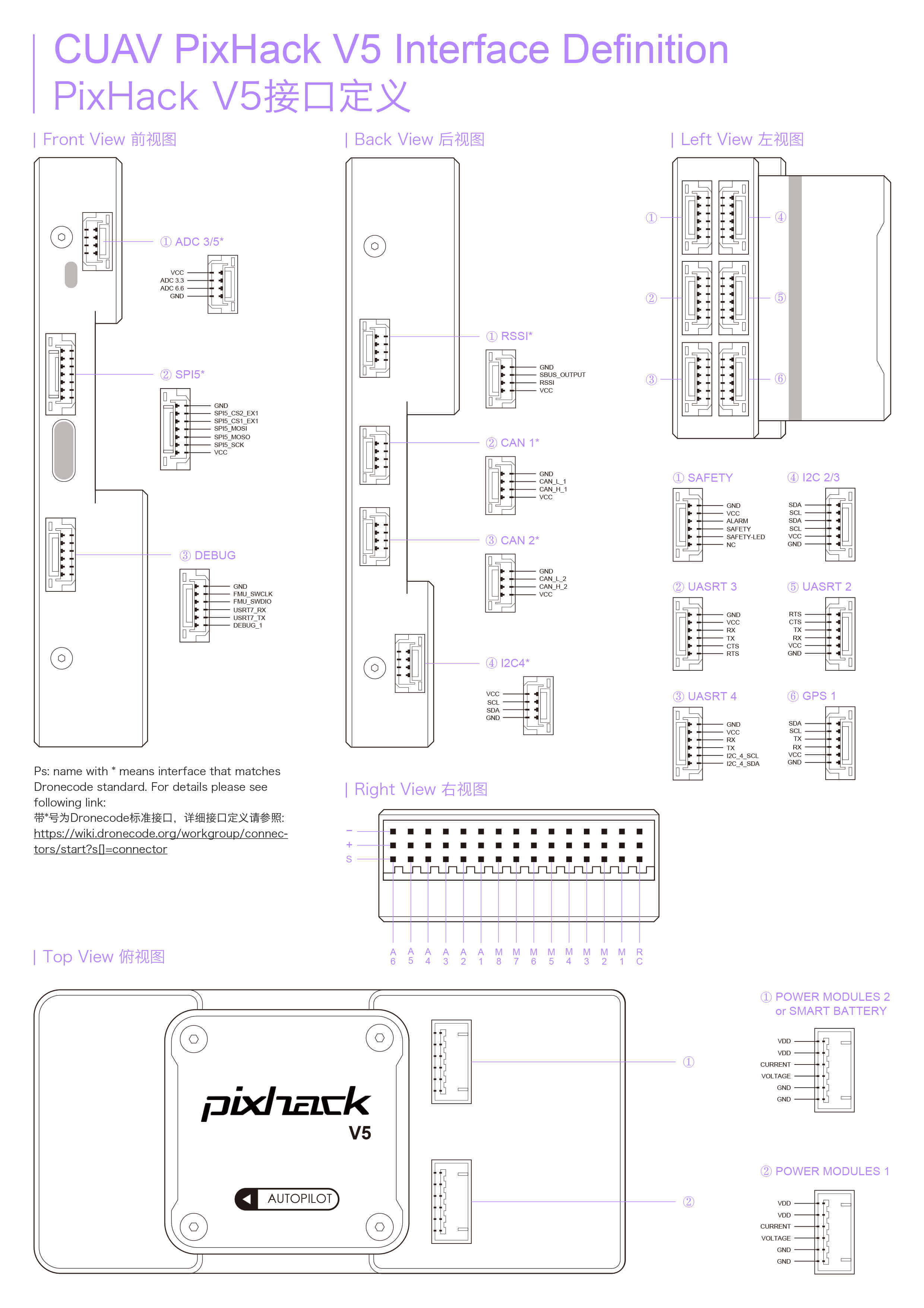
UART Mapping
- SERIAL0 -> USB
- SERIAL1 -> UART2 (Telem1)
- SERIAL2 -> UART3 (Telem2)
- SERIAL3 -> UART1 (GPS)
- SERIAL4 -> UART4 (GPS2)
- SERIAL5 -> UART6 (spare)
- SERIAL6 -> UART7 (spare, debug)
The Telem1 and Telem2 ports have RTS/CTS pins, the other UARTs do not have RTS/CTS.
The UART7 connector is labelled debug, but is available as a general purpose UART with ArduPilot.
RC Input
RC input is configured on the RCIN pin, at one end of the servo rail, marked RC in the above diagram. This pin supports all RC protocols.
PWM Output
The CUAVv5 supports up to 14 PWM outputs. First first 8 outputs (labelled "MAIN") are controlled by a dedicated STM32F100 IO controller. These 8 outputs support all PWM output formats, but not DShot.
The remaining 6 outputs (labelled AUX1 to AUX6) are the "auxillary" outputs. These are directly attached to the STM32F765 and support all PWM protocols as well as DShot.
All 14 PWM outputs have GND on the top row, 5V on the middle row and signal on the bottom row.
The 8 main PWM outputs are in 3 groups:
- PWM 1 and 2 in group1
- PWM 3 and 4 in group2
- PWM 5, 6, 7 and 8 in group3
The 6 auxillary PWM outputs are in 2 groups:
- PWM 1, 2, 3 and 4 in group1
- PWM 5 and 6 in group2
Channels within the same group need to use the same output rate. If any channel in a group uses DShot then all channels in the group need to use DShot.
Battery Monitoring
The board has two dedicated power monitor ports on 6 pin connectors. The correct battery setting parameters are dependent on the type of power brick which is connected.
Compass
The CUAVv5 has a builtin IST8310 compass. Due to potential interference the board is usually used with an external I2C compass as part of a GPS/Compass combination.
GPIOs
The 6 PWM ports can be used as GPIOs (relays, buttons, RPM etc). To use them you need to limit the number of these pins that is used for PWM by setting the BRD_PWM_COUNT to a number less than 6. For example if you set BRD_PWM_COUNT to 4 then PWM5 and PWM6 will be available for use as GPIOs.
The numbering of the GPIOs for PIN variables in ArduPilot is:
- AUX1 50
- AUX2 51
- AUX3 52
- AUX4 53
- AUX5 54
- AUX6 55
Analog inputs
The CUAVv5 has 7 analog inputs
- ADC Pin0 -> Battery Voltage
- ADC Pin1 -> Battery Current Sensor
- ADC Pin2 -> Battery Voltage 2
- ADC Pin3 -> Battery Current Sensor 2
- ADC Pin4 -> ADC port pin 2
- ADC Pin14 -> ADC port pin 3
- ADC Pin10 -> ADC 5V Sense
- ADC Pin11 -> ADC 3.3V Sense
- ADC Pin103 -> RSSI voltage monitoring
Loading Firmware
The board comes pre-installed with an ArduPilot compatible bootloader, allowing the loading of *.apj firmware files with any ArduPilot compatible ground station.
Acknowledgements
Thanks to CUAV for images